THE UX OF FINAL MAJOR PROJECT | BLOG 10
Crafting & Protyping & Testing
14/07/21 – 25/11/21 (about 3 months - excluding summer holidays)


 Design Brief: Materialise the obscurity and complexity of the Blockchain System.
Project Member: Yiwei(David) Han, Sue Heeyeon An.

Design Phase


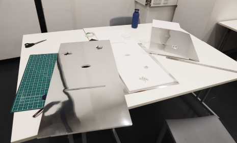
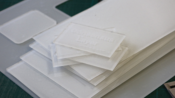
Sourcing materials (Courstey of David).
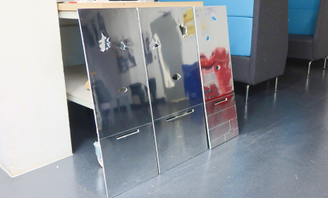
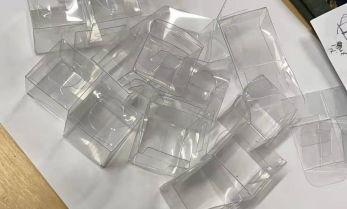
Once the final concept plan was sorted out, Sue and I had a clear collaboration and division of tasks. We would work together to purchase the required materials and produce them. For the choice of material, we decided to use transparent acrylic sheet as the material for the application layer to reflect the characteristic that it is the only one visible to the user. Mirror paper was used as the surface for the invisible layers (layers other than the application layer) to reflect their invisible character.
During this phase, I will be primarily responsible for the design and implementation of the interactive technology (i.e. including light encryption for the application layer, multi-person authentication for the consensus layer, and light network synchronisation effects for the network layer), while she will be primarily responsible for the design of the visual presentation component (including the appearance and layout and description of the application layer, and the layout and design of the key questions booklet).
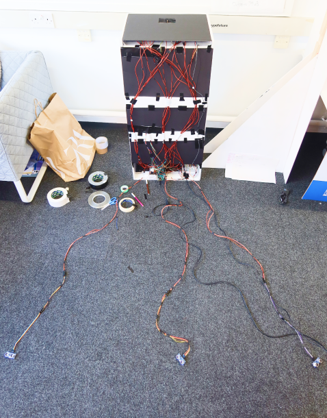
Finally, we will continue to make the components needed for each layer together (including soldering parts, finishing wires, fixing components, etc.) and assembling them into a whole. The following is our entire production process (shown in structural rather than chronological order):
Making Three Sides of the Installation Body
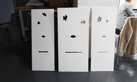
Measuring, cutting and punching: to create the three sides needed (Courtesy of David).
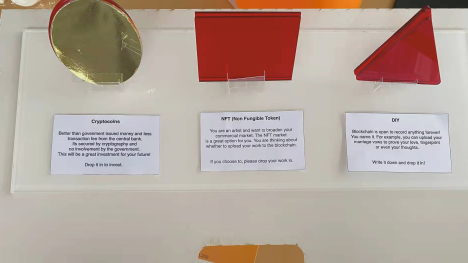
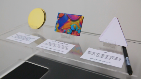
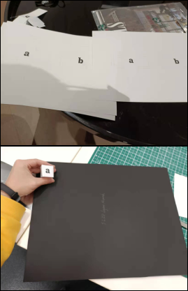
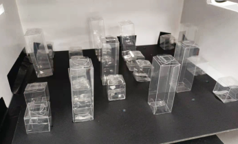
Making First Layer - Applicaiton Layer
Laser cutting, gluing, preparation of descriptions, packaging of items (Courtesy of David & Sue).
(Courtesy of Sue)
(Courtesy of Sue)
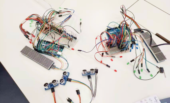
Second Layer - Data/Encryption Layer
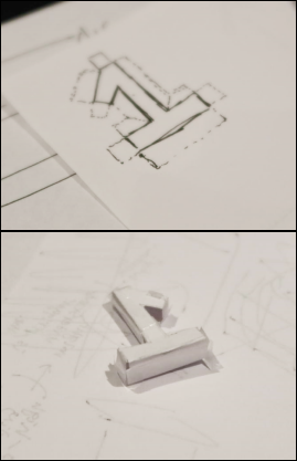
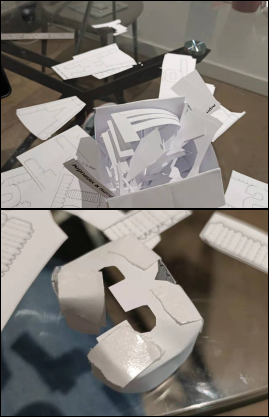
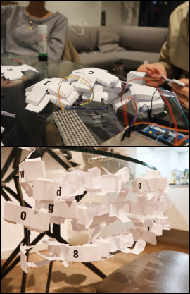
Making a three-dimensional string (first two attempts failed, ended up with a third approach), figuring out the LED light-up code and connecting the Arduino
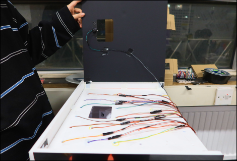
Wiring, Attaching LEDs and Switch & Taping them
The Sensitive Switch
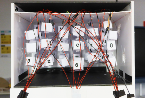
Data Layer inner look
(All courtesy of David).
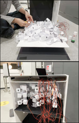
Third Layer & Forth Layer - Consensus Layer & Network Layer
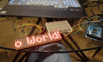
Prototype 01 - Show Text
Prototype 02 - Activate Text
Get all the components
Get materials for Network Layer LEDs
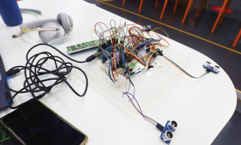
Wiring & Checking
Prototype 03 - Sensor Detected

Prepare Approval Area
Glue them at designated place
Consensus Layer inner look
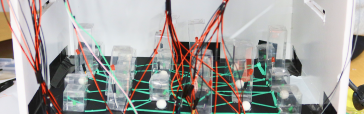
Network Layer inner look
(All courtesy of David).
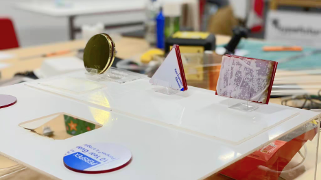
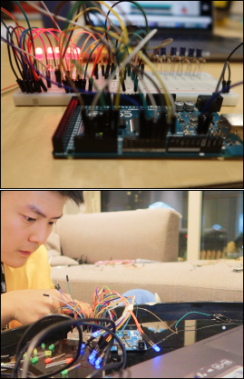
Assembling & Encapsulating
Soldering

Connecting 2nd Arduino & Testing
Connecting the first Arduino & Testing
Fixing each part and component & Encapsulating
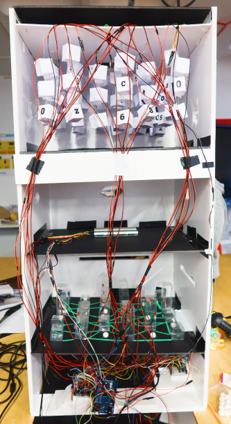
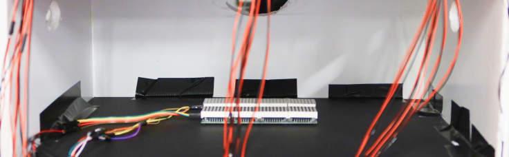
Interior view-the back of the installation
Encapsulated backside
(All courtesy of David).
This is a very time consuming process as it requires us to double check and ensure that we are doing each step correctly. Whether it's fixing the parts in place with glue, soldering the lights and the sensors, wiring them up or finally assembling them, if something goes wrong at one step, i.e. fixing them in an inappropriate position; soldering fails; wiring fails; circuit malfunction etc., we need to go through it all again. This experience was a great training of care and patience. Fortunately, we finally made it work after countless failures.
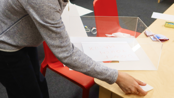
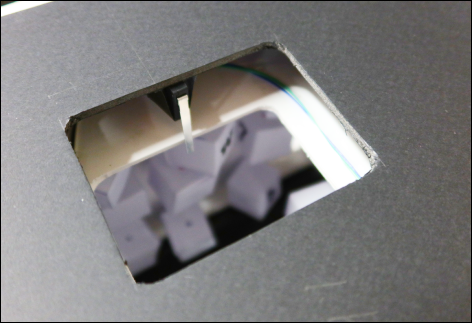
Tossing Testing
Round and triangular items can be successfully thrown in, but rectangles have the potential to get stuck. So I resized the throwing opening (Courtesy of David).
Coding
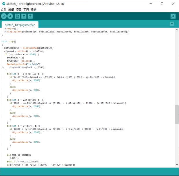
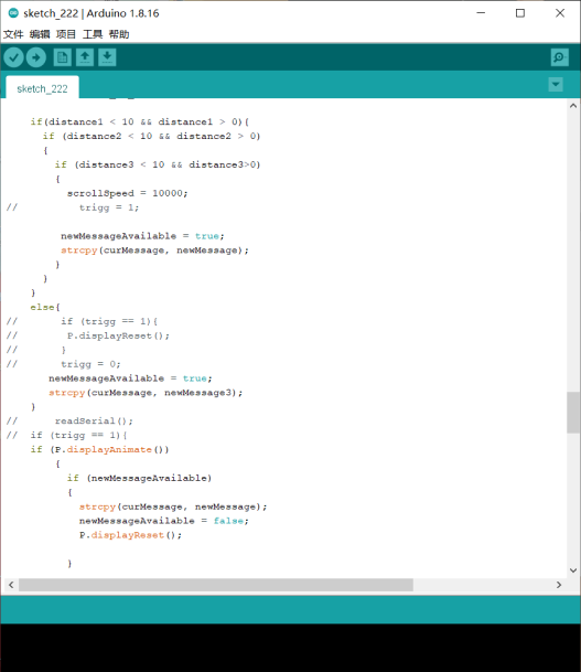
Key parts of the code: LEDs and sensors (Courtesy of David).
The main difficulty with this code is that it is not possible to use delay-related code to achieve a delayed flashing effect of the lights due to the electronic screen. Secondly, how to connect three sensors at the same time with one arduino and make an identification of each. The last problem was how to implement the various situations with conditional functions. (1.when someone is in the sensing area; 2.when no one is in the sensing area; 3.when someone is in the sensing area for a while but leaves; 4.when there are multiple people in the sensing area). I tried many different codes for this part and failed many times, but finally came up with the workable result. Many thanks also to Elle, the CTL technician, for her patient support.
In the coming week, we will invite potential target groups for a final experience test and concept video shoot.
Reference
Nasir, S.Z. (2015). Interfacing of Multiple Ultrasonic Sensor With Arduino. [online] The Engineering Projects. Available at: https://www.theengineeringprojects.com/2015/02/interfacing-multiple-ultrasonic-sensor-arduino.html [Accessed 21 Nov. 2021].